Startup power higher than while program running - why?


Closed Thread
Results 1 to 14 of 14
  1. #1
    Join Date
    Aug 2006
    Location
    SWITZERLAND (french speaking)
    Posts
    937

    Default Startup power higher than while program running - why?

    Hello,

    I'm finishing my timer project and I have started to measure power consumption to correctly dimention the power supply on the final PCB.

    When I power-up my circuit, the Amp-meter says 50mA. The timer is in some kind of idle mode since it waits for a player to start the timer or to choose the numbers of players.

    When a button has been pressed, the current drops down to 19mA (!?) and stays around this value for all the time the game is ongoing.

    In the START loop, pressing the RED button will ask the user to choose how many players will play. When it comes back to the initial display (still in the START loop), the current has dropped to 19mA (!?).

    I can software reset the game (no power OFF) so the timer can come back to the very starting point of the program = same point as when the circuit is powered-on. The current goes then back to 50mA.

    I assume something is wrong in my "START" loop.

    Yes but what???

    I had to attach the code in a .TXT file since it was to big to be fit in the post.

    PS: it's my first "real" program so critics & comments are really welcome
    Attached Files Attached Files
    Last edited by flotulopex; - 9th December 2006 at 13:38.
    Roger

  2. #2
    Join Date
    Aug 2006
    Location
    SWITZERLAND (french speaking)
    Posts
    937


    Did you find this post helpful? Yes | No

    Default Something with the Piezo

    So,

    After a removed things one-by-one I could define that something is wrong with the Piezo speaker I have.

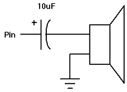
    Originally, the piezo was connected directly to the PIC's pin with a 1µF cap in parallel with the piezo.

    Since I removed the piezo, the current is constant at 19mA.

    In the PBP Compiler Manual, it says that you can connect a piezo directly to the PIC. But the sound is not good (like saturated).

    How do I have to connect my piezo a correct way?
    Roger

  3. #3
    Join Date
    Oct 2004
    Location
    Italy
    Posts
    695


    Did you find this post helpful? Yes | No

    Default

    Hi,

    Try first with 1μF and then with 10μF:


    Best regards,

    Luciano
    Last edited by Luciano; - 9th December 2006 at 16:46.

  4. #4
    Join Date
    Aug 2006
    Location
    SWITZERLAND (french speaking)
    Posts
    937


    Did you find this post helpful? Yes | No

    Default 1µF looks good!

    Tchao Luciano,

    The 1µF cap looks good! A 10µF one makes it even worse...

    Still making some more tests...

    Thanks a lot.
    Roger

  5. #5
    Join Date
    Oct 2004
    Location
    Italy
    Posts
    695


    Did you find this post helpful? Yes | No

    Default

    Hi,

    Disconnect the piezo from the microcontroller.
    Connect the piezo to +5V via the 1µF DC blocking
    capacitor and measure the current.

    * * *

    Connect the piezo to the microcontroller.
    With an oscilloscope measure what you have
    on the pin used to drive the piezo speaker.
    (Measure when you don't hear the piezo speaker).

    Best regards,

    Luciano

  6. #6
    Join Date
    Feb 2005
    Location
    Kolkata-India
    Posts
    563


    Did you find this post helpful? Yes | No

    Default Initialize your variables and ports

    Hi,

    You mentioned that the current drops when you start the program and fall into the main loop. PBP does not inititialize a variable and it can have arbitary values. When you use the SOUND command for the first time it sets the data direction registers. (Actually it does it every time). So either initialize your variables,Data Direction Registers and PORT Latches or just use a short sound before you fall into the start loop. Do this without the cap and with it post the results.
    Regards

    Sougata

  7. #7
    Join Date
    Aug 2006
    Location
    SWITZERLAND (french speaking)
    Posts
    937


    Did you find this post helpful? Yes | No

    Default Results

    OKay now,

    After y few different tries, I connected: PIC - 1µF - Piezo - R33 - Vss.

    Sound is very good; current drawn by piezo is about 8mA.

    I have attached both signals results (signal directly from PIC and signal after the 1µF cap).

    Sougata,

    I've tried to do as you said. But without the cap, it just does the same as before (current stays 50mA until I press a button).

    I don't understand your comment about the variables initialisation. Is my "INIT" piece of code not correct?
    Attached Images Attached Images     
    Roger

  8. #8
    Join Date
    Feb 2005
    Location
    Kolkata-India
    Posts
    563


    Did you find this post helpful? Yes | No

    Default Set your Buzzer port to low

    Hi,

    As you mentioned that after you press a button then the current goes down. You have also found out that it is the buzzer that is drawing the current. So when you are starting up your PIC if the port is set to an output you expect a low. If that was true then with the other end connected to VSS rules out any possibilities of drawing current. So the port is not low as expected. This is what I meant. You should always setup the initial states of the port yourself. The capacitor is acting as a DC blocking only and thus even if your port is high at startup it prevent current draw from the PIC. An interesting phenomena could be excessive switching noise at the PIC port (which starts as a input by default ), your buzzer can actually create signal if it is vibrated. Connect your scope to its ends and tap it to see for yourself. But that will not cause so much of current drain due to the internal CMOS structure switching with noise. So I still doubt what is the state of the pin when first start it up. 16F88 has got onboard peripherals which are connected to the same pin. Hope I have made myself clear this time.
    Regards

    Sougata

  9. #9
    Join Date
    Feb 2005
    Location
    Kolkata-India
    Posts
    563


    Did you find this post helpful? Yes | No

    Default Set your Buzzer port to low

    Hi,

    As you mentioned that after you press a button then the current goes down. You have also found out that it is the buzzer that is drawing the current. So when you are starting up your PIC if the port is set to an output you expect a low. If that was true then with the other end connected to VSS rules out any possibilities of drawing current. So the port is not low as expected. This is what I meant. You should always setup the initial states of the port yourself. The capacitor is acting as a DC blocking only and thus even if your port is high at startup it prevent current draw from the PIC. An interesting phenomena could be excessive switching noise at the PIC port (which starts as a input by default ), your buzzer can actually create signal if it is vibrated. Connect your scope to its ends and tap it to see for yourself. But that will not cause so much of current drain due to the internal CMOS structure switching with noise. So I still doubt what is the state of the pin when first start it up. 16F88 has got onboard peripherals which are connected to the same pin. Hope I have made myself clear this time.
    Regards

    Sougata

  10. #10
    Join Date
    Aug 2006
    Location
    SWITZERLAND (french speaking)
    Posts
    937


    Did you find this post helpful? Yes | No

    Default Okay, I'll init it LOW

    Okay, I'll init it LOW.

    It was now clear to me.

    Checking this out now...

    You're right - now it works fine.

    Actually, I noticed that all PORTBs are driven HIGH for one second when I power-up the circuit. I initilize them to LOW but this happens after the register setting.

    I don't think it would make sense to set the PORTBs LOW before the registers are set, does it?
    Roger

  11. #11
    Join Date
    Feb 2005
    Location
    Kolkata-India
    Posts
    563


    Did you find this post helpful? Yes | No

    Default Try this

    Hi,

    Could you please insert the following lines in your register settings:

    Code:
    SSPCON.5   = 0                  ' DISABLE THE SYNC.SERIAL.PORT AND USE AS I/O
    TRISB      = %11000000
    PORTB      = 0                  ' Init PORTB to low
    Portb.5 is shared with the onboard Synchronous Serial Port. Turning off bit 5 of the SSPCON registers turns off this peripheral and configures it as general I/O.
    Regards

    Sougata

  12. #12
    Join Date
    Aug 2006
    Location
    SWITZERLAND (french speaking)
    Posts
    937


    Did you find this post helpful? Yes | No

    Default Default register settings

    Sougata,

    I think my SSPCON register is already set but, just to make sure, am I right to say that in the PIC's datasheet, the register settings have default values I can read like here "R/W-0" and it would mean that the bit is set to 0?

    Code:
    REGISTER 10-2: SSPCON: SYNCHRONOUS SERIAL PORT CONTROL REGISTER (ADDRESS 14h)
    R/W-0 R/W-0 R/W-0   R/W-0 R/W-0 R/W-0 R/W-0 R/W-0
    WCOL  SSPOV SSPEN(1)CKP   SSPM3 SSPM2 SSPM1 SSPM0
    bit 7                                       bit 0
    Roger

  13. #13
    Join Date
    Feb 2005
    Location
    Kolkata-India
    Posts
    563


    Did you find this post helpful? Yes | No

    Default You are right

    Hi,

    The default when the PIC starts is SSPCON turned off. But you mentioned that your portb is keeping high for sometime from start. There has to be a logical reason why. I do not have a 16F88 lying so cannot give it a try myself. May be I should give a closer look to your code.
    Regards

    Sougata

  14. #14
    Join Date
    Aug 2006
    Location
    SWITZERLAND (french speaking)
    Posts
    937


    Did you find this post helpful? Yes | No

    Default

    Sougata,

    Thank you for confirmation.

    As said in a previous post, I have solved the problem by putting a 1µF cap in serie with the BUZZER.
    Roger

Similar Threads

  1. Battery powered applications
    By NavMicroSystems in forum Off Topic
    Replies: 7
    Last Post: - 22nd June 2009, 08:12
  2. Pic getting part power from Analog Port
    By ShaneMichael in forum mel PIC BASIC Pro
    Replies: 7
    Last Post: - 22nd April 2009, 11:34
  3. Making Program Code Space your playground...
    By Melanie in forum Code Examples
    Replies: 15
    Last Post: - 19th July 2008, 09:26
  4. Replies: 4
    Last Post: - 16th May 2008, 15:35
  5. Program returns to beginning at interupt
    By BGreen in forum mel PIC BASIC Pro
    Replies: 5
    Last Post: - 25th April 2005, 12:20

Members who have read this thread : 0

You do not have permission to view the list of names.

Posting Permissions

  • You may not post new threads
  • You may not post replies
  • You may not post attachments
  • You may not edit your posts